| Single-stage Regulators
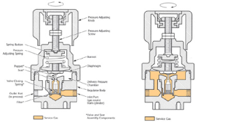
Gas enters the inlet (high pressure) chamber and its pressure is indicated on the inlet pressure gauge. When the pressure adjusting knob is turned counterclockwise and completely backed out to the stop (Figure 1), a valve and seat assembly located between the inlet chamber and the delivery (low pressure) chamber prevents gas from moving any further. A wire screen filter, located at the inlet to the valve and seat assembly, removes particulate matter from the gas stream to help protect the seat area. Turning the pressure adjusting knob clockwise (Figure 2) causes the adjusting screw to push against a spring button which compresses the pressure adjusting spring. The force of the compressed spring, in turn, causes the diaphragm to flex and push against the poppet. This opens the regulator allowing gas to flow from the inlet chamber to the delivery chamber of the regulator. Gas entering the delivery pressure chamber begins to build pressure and creates a counter-force (counter to the pressure adjusting spring) on the diaphragm. This pressure is indicated on the delivery pressure gauge attached to the delivery chamber. When pressure builds sufficiently to counteract the spring tension, it pushes the diaphragm away from the poppet allowing the regulator to close. In this manner, pressure in the delivery chamber is controlled or regulated by the amount of spring tension placed on the diaphragm, and is selectable by turning the pressure adjusting knob until desired pressure is indicated on the delivery pressure gauge. When gas from the delivery pressure chamber is sent to the end process, the resulting decrease in gas volume in the delivery chamber causes a pressure reduction in the chamber. When this occurs, the spring tension again causes the diaphragm to push the poppet open, allowing additional gas to enter the delivery chamber. Two-stage Regulators
Because of the two-step pressure reduction, final delivery pressure of a two-stage regulator shows little effect from changes in cylinder pressure. |